1. Introduction
The process of attaching substances (raw materials) to the surface of substrate materials by physical or chemical methods is called thin film growth.
According to different working principles, integrated circuit thin film deposition can be divided into:
-Physical Vapor Deposition (PVD);
-Chemical Vapor Deposition (CVD);
-Extension.
2. Thin Film Growth Process
2.1 Physical vapor deposition and sputtering process
The physical vapor deposition (PVD) process refers to the use of physical methods such as vacuum evaporation, sputtering, plasma coating and molecular beam epitaxy to form a thin film on the surface of a wafer.
In the VLSI industry, the most widely used PVD technology is sputtering, which is mainly used for electrodes and metal interconnects of integrated circuits. Sputtering is a process in which rare gases [such as argon (Ar)] are ionized into ions (such as Ar+) under the action of an external electric field under high vacuum conditions, and bombard the material target source under a high voltage environment, knocking out atoms or molecules of the target material, and then arriving at the surface of the wafer to form a thin film after a collision-free flight process. Ar has stable chemical properties, and its ions will not react chemically with the target material and the film. As integrated circuit chips enter the 0.13μm copper interconnect era, the copper barrier material layer uses titanium nitride (TiN) or tantalum nitride (TaN) film. The demand for industrial technology has promoted the research and development of chemical reaction sputtering technology, that is, in the sputtering chamber, in addition to Ar, there is also a reactive gas nitrogen (N2), so that the Ti or Ta bombarded from the target material Ti or Ta reacts with N2 to generate the required TiN or TaN film.
There are three commonly used sputtering methods, namely DC sputtering, RF sputtering and magnetron sputtering. As the integration of integrated circuits continues to increase, the number of layers of multi-layer metal wiring is increasing, and the application of PVD technology is becoming more and more extensive. PVD materials include Al-Si, Al-Cu, Al-Si-Cu, Ti, Ta, Co, TiN, TaN, Ni, WSi2, etc.
PVD and sputtering processes are usually completed in a highly sealed reaction chamber with a vacuum degree of 1×10⁻⁷ to 9×10⁻⁹ Torr, which can ensure the purity of the gas during the reaction; at the same time, an external high voltage is required to ionize the rare gas to generate a high enough voltage to bombard the target. The main parameters for evaluating PVD and sputtering processes include the amount of dust, as well as the resistance value, uniformity, reflectivity thickness and stress of the formed film.
2.2 Chemical Vapor Deposition and Sputtering Process
Chemical vapor deposition (CVD) refers to a process technology in which a variety of gaseous reactants with different partial pressures react chemically at a certain temperature and pressure, and the generated solid substances are deposited on the surface of the substrate material to obtain the desired thin film. In the traditional integrated circuit manufacturing process, the obtained thin film materials are generally compounds such as oxides, nitrides, carbides, or materials such as polycrystalline silicon and amorphous silicon. Selective epitaxial growth, which is more commonly used after the 45nm node, such as source and drain SiGe or Si selective epitaxial growth, is also a CVD technology.
This technology can continue to form single crystal materials of the same type or similar to the original lattice on a single crystal substrate of silicon or other materials along the original lattice. CVD is widely used in the growth of insulating dielectric films (such as SiO2, Si3N4 and SiON, etc.) and metal films (such as tungsten, etc.).
Generally, according to the pressure classification, CVD can be divided into atmospheric pressure chemical vapor deposition (APCVD), sub-atmosphere pressure chemical vapor deposition (SAPCVD) and low pressure chemical vapor deposition (LPCVD).
According to temperature classification, CVD can be divided into high temperature/low temperature oxide film chemical vapor deposition (HTO/LTO CVD) and rapid thermal chemical vapor deposition (Rapid Thermal CVD, RTCVD);
According to the reaction source, CVD can be divided into silane-based CVD, polyester-based CVD (TEOS-based CVD) and metal organic chemical vapor deposition (MOCVD);
According to energy classification, CVD can be divided into thermal chemical vapor deposition (Thermal CVD), plasma enhanced chemical vapor deposition (Plasma Enhanced CVD, PECVD) and high density plasma chemical vapor deposition (High Density Plasma CVD, HDPCVD). Recently, flowable chemical vapor deposition (Flowable CVD, FCVD) with excellent gap filling ability has also been developed.
Different CVD-grown films have different properties (such as chemical composition, dielectric constant, tension, stress and breakdown voltage) and can be used separately according to different process requirements (such as temperature, step coverage, filling requirements, etc.).
2.3 Atomic layer deposition process
Atomic layer deposition (ALD) refers to the deposition of atoms layer by layer on a substrate material by growing a single atomic film layer by layer. A typical ALD adopts the method of inputting gaseous precursors into the reactor in an alternating pulsed manner.
For example, first, the reaction precursor 1 is introduced into the substrate surface, and after chemical adsorption, a single atomic layer is formed on the substrate surface; then the precursor 1 remaining on the substrate surface and in the reaction chamber is pumped out by an air pump; then the reaction precursor 2 is introduced into the substrate surface, and chemically reacts with the precursor 1 adsorbed on the substrate surface to generate the corresponding thin film material and the corresponding by-products on the substrate surface; when the precursor 1 reacts completely, the reaction will automatically terminate, which is the self-limiting characteristic of ALD, and then the remaining reactants and by-products are extracted to prepare for the next stage of growth; by repeating the above process continuously, the deposition of thin film materials grown layer by layer with single atoms can be achieved.
Both ALD and CVD are ways of introducing a gaseous chemical reaction source to react chemically on the substrate surface, but the difference is that the gaseous reaction source of CVD does not have the characteristic of self-limiting growth. It can be seen that the key to developing ALD technology is to find precursors with self-limiting reaction properties.
2.4 Epitaxial Process
Epitaxial process refers to the process of growing a completely ordered single crystal layer on a substrate. Generally speaking, the epitaxial process is to grow a crystal layer with the same lattice orientation as the original substrate on a single crystal substrate. Epitaxial process is widely used in semiconductor manufacturing, such as epitaxial silicon wafers in the integrated circuit industry, embedded source and drain epitaxial growth of MOS transistors, epitaxial growth on LED substrates, etc.
According to the different phase states of the growth source, epitaxial growth methods can be divided into solid phase epitaxy, liquid phase epitaxy, and vapor phase epitaxy. In integrated circuit manufacturing, the commonly used epitaxial methods are solid phase epitaxy and vapor phase epitaxy.
Solid phase epitaxy: refers to the growth of a single crystal layer on a substrate using a solid source. For example, thermal annealing after ion implantation is actually a solid phase epitaxy process. During ion implantation, the silicon atoms of the silicon wafer are bombarded by high-energy implanted ions, leaving their original lattice positions and becoming amorphous, forming a surface amorphous silicon layer. After high-temperature thermal annealing, the amorphous atoms return to their lattice positions and remain consistent with the atomic crystal orientation inside the substrate.
The growth methods of vapor phase epitaxy include chemical vapor phase epitaxy, molecular beam epitaxy, atomic layer epitaxy, etc. In integrated circuit manufacturing, chemical vapor phase epitaxy is the most commonly used. The principle of chemical vapor phase epitaxy is basically the same as that of chemical vapor deposition. Both are processes that deposit thin films by chemically reacting on the surface of wafers after gas mixing.
The difference is that because chemical vapor phase epitaxy grows a single crystal layer, it has higher requirements for the impurity content in the equipment and the cleanliness of the wafer surface. The early chemical vapor phase epitaxial silicon process needs to be carried out under high temperature conditions (greater than 1000°C). With the improvement of process equipment, especially the adoption of vacuum exchange chamber technology, the cleanliness of the equipment cavity and the surface of the silicon wafer has been greatly improved, and silicon epitaxy can be carried out at a lower temperature (600-700°C). The epitaxial silicon wafer process is to grow a layer of single crystal silicon on the surface of the silicon wafer.
Compared with the original silicon substrate, the epitaxial silicon layer has higher purity and fewer lattice defects, thereby improving the yield of semiconductor manufacturing. In addition, the growth thickness and doping concentration of the epitaxial silicon layer grown on the silicon wafer can be flexibly designed, which brings flexibility to the design of the device , such as reducing substrate resistance and enhancing substrate isolation. The embedded source-drain epitaxial process is a technology widely used in advanced logic technology nodes.
It refers to the process of epitaxially growing doped germanium silicon or silicon in the source and drain regions of MOS transistors. The main advantages of introducing the embedded source-drain epitaxial process include: growing a pseudocrystalline layer containing stress due to lattice adaptation, improving channel carrier mobility; in-situ doping of the source and drain can reduce the parasitic resistance of the source-drain junction and reduce the defects of high-energy ion implantation.
3. thin film growth equipment
3.1 Vacuum evaporation equipment
Vacuum evaporation is a coating method that heats solid materials in a vacuum chamber to cause them to evaporate, vaporize or sublimate, and then condense and deposit on the surface of a substrate material at a certain temperature.
Usually it consists of three parts, namely the vacuum system, evaporation system and heating system. The vacuum system consists of vacuum pipes and vacuum pumps, and its main function is to provide a qualified vacuum environment for evaporation. The evaporation system consists of an evaporation table, a heating component and a temperature measurement component.
The target material to be evaporated (such as Ag, Al, etc.) is placed on the evaporation table; the heating and temperature measurement component is a closed-loop system used to control the evaporation temperature to ensure smooth evaporation. The heating system consists of a wafer stage and a heating component. The wafer stage is used to place the substrate on which the thin film needs to be evaporated, and the heating component is used to realize substrate heating and temperature measurement feedback control.
The vacuum environment is a very important condition in the vacuum evaporation process, which is related to the evaporation rate and the quality of the film. If the vacuum degree does not meet the requirements, the vaporized atoms or molecules will collide frequently with the residual gas molecules, making their mean free path smaller, and the atoms or molecules will scatter severely, thereby changing the direction of movement and reducing the film formation rate.
In addition, due to the presence of residual impurity gas molecules, the deposited film is seriously contaminated and of poor quality, especially when the pressure rise rate of the chamber does not meet the standard and there is leakage, air will leak into the vacuum chamber, which will have a serious impact on the film quality.
The structural characteristics of the vacuum evaporation equipment determine that the uniformity of the coating on large-size substrates is poor. In order to improve its uniformity, the method of increasing the source-substrate distance and rotating the substrate is generally adopted, but increasing the source-substrate distance will sacrifice the growth rate and purity of the film. At the same time, due to the increase in the vacuum space, the utilization rate of the evaporated material is reduced.
3.2 DC physical vapor deposition equipment
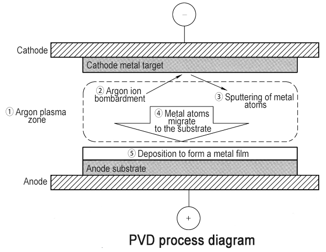
Direct current physical vapor deposition (DCPVD) is also known as cathode sputtering or vacuum DC two-stage sputtering. The target material of vacuum DC sputtering is used as the cathode and the substrate is used as the anode. Vacuum sputtering is to form a plasma by ionizing the process gas.
The charged particles in the plasma are accelerated in the electric field to obtain a certain amount of energy. The particles with sufficient energy bombard the surface of the target material, so that the target atoms are sputtered out; the sputtered atoms with a certain kinetic energy move toward the substrate to form a thin film on the surface of the substrate. The gas used for sputtering is generally a rare gas, such as argon (Ar), so the film formed by sputtering will not be contaminated; in addition, the atomic radius of argon is more suitable for sputtering.
The size of the sputtering particles must be close to the size of the target atoms to be sputtered. If the particles are too large or too small, effective sputtering cannot be formed. In addition to the size factor of the atom, the mass factor of the atom will also affect the sputtering quality. If the sputtering particle source is too light, the target atoms will not be sputtered; if the sputtering particles are too heavy, the target will be “bent” and the target will not be sputtered.
The target material used in DCPVD must be a conductor. This is because when the argon ions in the process gas bombard the target material, they will recombine with the electrons on the surface of the target material. When the target material is a conductor such as a metal, the electrons consumed by this recombination are more easily replenished by the power supply and free electrons in other parts of the target material through electrical conduction, so that the surface of the target material as a whole remains negatively charged and sputtering is maintained.
On the contrary, if the target material is an insulator, after the electrons on the surface of the target material are recombinated, the free electrons in other parts of the target material cannot be replenished by electrical conduction, and even positive charges will accumulate on the surface of the target material, causing the target material potential to rise, and the negative charge of the target material is weakened until it disappears, eventually leading to the termination of sputtering.
Therefore, in order to make insulating materials also usable for sputtering, it is necessary to find another sputtering method. Radio frequency sputtering is a sputtering method that is suitable for both conductive and non-conductive targets.
Another disadvantage of DCPVD is that the ignition voltage is high and the electron bombardment on the substrate is strong. An effective way to solve this problem is to use magnetron sputtering, so magnetron sputtering is really of practical value in the field of integrated circuits.
3.3 RF Physical Vapor Deposition Equipment
Radio frequency physical vapor deposition (RFPVD) uses radio frequency power as the excitation source and is a PVD method suitable for a variety of metal and non-metal materials.
The common frequencies of the RF power supply used in RFPVD are 13.56MHz, 20MHz, and 60MHz. The positive and negative cycles of the RF power supply appear alternately. When the PVD target is in the positive half cycle, because the target surface is at a positive potential, the electrons in the process atmosphere will flow to the target surface to neutralize the positive charge accumulated on its surface, and even continue to accumulate electrons, making its surface negatively biased; when the sputtering target is in the negative half cycle, the positive ions will move toward the target and be partially neutralized on the target surface.
The most critical thing is that the movement speed of electrons in the RF electric field is much faster than that of positive ions, while the time of the positive and negative half cycles is the same, so after a complete cycle, the target surface will be “net” negatively charged. Therefore, in the first few cycles, the negative charge of the target surface shows an increasing trend; afterwards, the target surface reaches a stable negative potential; thereafter, because the negative charge of the target has a repulsive effect on electrons, the amount of positive and negative charges received by the target electrode tends to balance, and the target presents a stable negative charge.
From the above process, it can be seen that the process of negative voltage formation has nothing to do with the properties of the target material itself, so the RFPVD method can not only solve the problem of sputtering of insulating targets, but also is well compatible with conventional metal conductor targets.
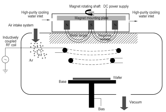
3.4 Magnetron sputtering equipment
Magnetron sputtering is a PVD method that adds magnets to the back of the target. The added magnets and the DC power supply (or AC power supply) system form a magnetron sputtering source. The sputtering source is used to form an interactive electromagnetic field in the chamber, capture and limit the movement range of electrons in the plasma inside the chamber, extend the movement path of electrons, and thus increase the concentration of the plasma, and ultimately achieve more deposition.
In addition, because more electrons are bound near the surface of the target, the bombardment of the substrate by electrons is reduced, and the temperature of the substrate is reduced. Compared with the flat-plate DCPVD technology, one of the most obvious features of magnetron physical vapor deposition technology is that the ignition discharge voltage is lower and more stable.
Because of its higher plasma concentration and larger sputtering yield, it can achieve excellent deposition efficiency, deposition thickness control in a large size range, precise composition control and lower ignition voltage. Therefore, magnetron sputtering is in a dominant position in the current metal film PVD. The simplest magnetron sputtering source design is to place a group of magnets on the back of the flat target (outside the vacuum system) to generate a magnetic field parallel to the target surface in a local area on the target surface.
If a permanent magnet is placed, its magnetic field is relatively fixed, resulting in a relatively fixed magnetic field distribution on the target surface in the chamber. Only materials in specific areas of the target are sputtered, the target utilization rate is low, and the uniformity of the prepared film is poor.
There is a certain probability that the sputtered metal or other material particles will be deposited back on the target surface, thereby aggregating into particles and forming defect contamination. Therefore, commercial magnetron sputtering sources mostly use a rotating magnet design to improve film uniformity, target utilization rate, and full target sputtering.
It is crucial to balance these three factors. If the balance is not handled well, it may result in a good film uniformity while greatly reducing the target utilization rate (shortening the target life), or failing to achieve full target sputtering or full target corrosion, which will cause particle problems during the sputtering process.
In magnetron PVD technology, it is necessary to consider the rotating magnet movement mechanism, target shape, target cooling system and magnetron sputtering source, as well as the functional configuration of the base that carries the wafer, such as wafer adsorption and temperature control. In the PVD process, the temperature of the wafer is controlled to obtain the required crystal structure, grain size and orientation, as well as the stability of performance.
Since the heat conduction between the back of the wafer and the surface of the base requires a certain pressure, usually in the order of several Torr, and the working pressure of the chamber is usually in the order of several mTorr, the pressure on the back of the wafer is much greater than the pressure on the upper surface of the wafer, so a mechanical chuck or an electrostatic chuck is needed to position and limit the wafer.
The mechanical chuck relies on its own weight and the edge of the wafer to achieve this function. Although it has the advantages of simple structure and insensitivity to the material of the wafer, the edge effect of the wafer is obvious, which is not conducive to the strict control of particles. Therefore, it has been gradually replaced by an electrostatic chuck in the IC manufacturing process.
For processes that are not particularly sensitive to temperature, a non-adsorption, non-edge contact shelving method (no pressure difference between the upper and lower surfaces of the wafer) can also be used. During the PVD process, the chamber lining and the surface of the parts in contact with the plasma will be deposited and covered. When the deposited film thickness exceeds the limit, the film will crack and peel off, causing particle problems.
Therefore, the surface treatment of parts such as the lining is the key to extending this limit. Surface sandblasting and aluminum spraying are two commonly used methods, the purpose of which is to increase the surface roughness to strengthen the bonding between the film and the lining surface.
3.5 Ionization Physical Vapor Deposition Equipment
With the continuous development of microelectronics technology, feature sizes are becoming smaller and smaller. Since PVD technology cannot control the deposition direction of particles, the ability of PVD to enter through holes and narrow channels with high aspect ratios is limited, making the expanded application of traditional PVD technology increasingly challenged. In the PVD process, as the aspect ratio of the pore groove increases, the coverage at the bottom decreases, forming an eaves-like overhanging structure at the top corner, and forming the weakest coverage at the bottom corner.
Ionized physical vapor deposition technology was developed to solve this problem. It first plasmatizes the metal atoms sputtered from the target in different ways, and then adjusts the bias voltage loaded on the wafer to control the direction and energy of the metal ions to obtain a stable directional metal ion flow to prepare a thin film, thereby improving the coverage of the bottom of the steps of high aspect ratio through holes and narrow channels.
The typical feature of ionized metal plasma technology is the addition of a radio frequency coil in the chamber. During the process, the working pressure of the chamber is maintained at a relatively high state (5 to 10 times the normal working pressure). During PVD, the radio frequency coil is used to generate the second plasma region, in which the argon plasma concentration increases with the increase of radio frequency power and gas pressure. When the metal atoms sputtered from the target pass through this region, they interact with the high-density argon plasma to form metal ions.
Applying an RF source at the wafer carrier (such as an electrostatic chuck) can increase the negative bias on the wafer to attract metal positive ions to the bottom of the pore groove. This directional metal ion flow perpendicular to the wafer surface improves the step bottom coverage of high aspect ratio pores and narrow channels.
The negative bias applied to the wafer also causes ions to bombard the wafer surface (reverse sputtering), which weakens the overhanging structure of the pore groove mouth and sputters the film deposited at the bottom onto the sidewalls at the corners of the bottom of the pore groove, thereby enhancing the step coverage at the corners.
3.6 Atmospheric Pressure Chemical Vapor Deposition Equipment
Atmospheric pressure chemical vapor deposition (APCVD) equipment refers to a device that sprays a gaseous reaction source at a constant speed onto the surface of a heated solid substrate under an environment with a pressure close to atmospheric pressure, causing the reaction source to react chemically on the substrate surface, and the reaction product is deposited on the substrate surface to form a thin film.
APCVD equipment is the earliest CVD equipment and is still widely used in industrial production and scientific research. APCVD equipment can be used to prepare thin films such as single crystal silicon, polycrystalline silicon, silicon dioxide, zinc oxide, titanium dioxide, phosphosilicate glass, and borophosphosilicate glass.
3.7 Low Pressure Chemical Vapor Deposition Equipment
Low-pressure chemical vapor deposition (LPCVD) equipment refers to equipment that uses gaseous raw materials to react chemically on the surface of a solid substrate under a heated (350-1100°C) and low-pressure (10-100mTorr) environment, and the reactants are deposited on the substrate surface to form a thin film. LPCVD equipment is developed on the basis of APCVD to improve the quality of thin films, improve the distribution uniformity of characteristic parameters such as film thickness and resistivity, and improve production efficiency.
Its main feature is that in a low-pressure thermal field environment, the process gas reacts chemically on the surface of the wafer substrate, and the reaction products are deposited on the substrate surface to form a thin film. LPCVD equipment has advantages in the preparation of high-quality thin films and can be used to prepare thin films such as silicon oxide, silicon nitride, polysilicon, silicon carbide, gallium nitride and graphene.
Compared with APCVD, the low-pressure reaction environment of LPCVD equipment increases the mean free path and diffusion coefficient of the gas in the reaction chamber.
The reaction gas and carrier gas molecules in the reaction chamber can be evenly distributed in a short time, thus greatly improving the uniformity of film thickness, resistivity uniformity and step coverage of the film, and the consumption of reaction gas is also small. In addition, the low-pressure environment also speeds up the transmission speed of gas substances. Impurities and reaction by-products diffused from the substrate can be quickly taken out of the reaction zone through the boundary layer, and the reaction gas quickly passes through the boundary layer to reach the substrate surface for reaction, thus effectively suppressing self-doping, preparing high-quality films with steep transition zones, and also improving production efficiency.
3.8 Plasma Enhanced Chemical Vapor Deposition Equipment
Plasma enhanced chemical vapor deposition (PECVD) is a widely used thin film deposition technology. During the plasma process, the gaseous precursor is ionized under the action of plasma to form excited active groups, which diffuse to the substrate surface and then undergo chemical reactions to complete the film growth.
According to the frequency of plasma generation, the plasma used in PECVD can be divided into two types: radio frequency plasma (RF plasma) and microwave plasma (Microwave plasma). At present, the radio frequency used in the industry is generally 13.56MHz.
The introduction of radio frequency plasma is usually divided into two types: capacitive coupling (CCP) and inductive coupling (ICP). The capacitive coupling method is usually a direct plasma reaction method; while the inductive coupling method can be a direct plasma method or a remote plasma method.
In semiconductor manufacturing processes, PECVD is often used to grow thin films on substrates containing metals or other temperature-sensitive structures. For example, in the field of back-end metal interconnection of integrated circuits, since the source, gate and drain structures of the device have been formed in the front-end process, the growth of thin films in the field of metal interconnection is subject to very strict thermal budget constraints, so it is usually completed with plasma assistance. By adjusting the plasma process parameters, the density, chemical composition, impurity content, mechanical toughness and stress parameters of the thin film grown by PECVD can be adjusted and optimized within a certain range.
3.9 Atomic Layer Deposition Equipment
Atomic layer deposition (ALD) is a thin film deposition technology that grows periodically in the form of a quasi-monoatomic layer. Its characteristic is that the thickness of the deposited film can be precisely adjusted by controlling the number of growth cycles. Unlike the chemical vapor deposition (CVD) process, the two (or more) precursors in the ALD process alternately pass through the substrate surface and are effectively isolated by the purge of rare gas.
The two precursors will not mix and meet in the gas phase to react chemically, but only react through chemical adsorption on the substrate surface. In each ALD cycle, the amount of precursor adsorbed on the substrate surface is related to the density of the active groups on the substrate surface. When the reactive groups on the substrate surface are exhausted, even if an excess of precursor is introduced, chemical adsorption will not occur on the substrate surface.
This reaction process is called a surface self-limiting reaction. This process mechanism makes the thickness of the film grown in each cycle of the ALD process constant, so the ALD process has the advantages of precise thickness control and good film step coverage.
3.10 Molecular Beam Epitaxy Equipment
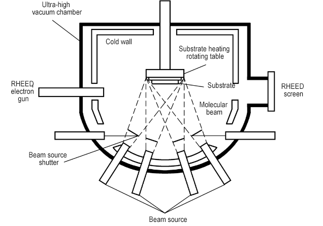
Molecular Beam Epitaxy (MBE) system refers to an epitaxial device that uses one or more thermal energy atomic beams or molecular beams to spray onto the heated substrate surface at a certain speed under ultra-high vacuum conditions, and adsorb and migrate on the substrate surface to epitaxially grow single crystal thin films along the crystal axis direction of the substrate material. Generally, under the condition of heating by a jet furnace with a heat shield, the beam source forms an atomic beam or a molecular beam, and the film grows layer by layer along the crystal axis direction of the substrate material.
Its characteristics are low epitaxial growth temperature, and the thickness, interface, chemical composition and impurity concentration can be precisely controlled at the atomic level. Although MBE originated from the preparation of semiconductor ultra-thin single crystal films, its application has now expanded to a variety of material systems such as metals and insulating dielectrics, and can prepare III-V, II-VI, silicon, silicon germanium (SiGe), graphene, oxides and organic films.
The molecular beam epitaxy (MBE) system is mainly composed of an ultra-high vacuum system, a molecular beam source, a substrate fixing and heating system, a sample transfer system, an in-situ monitoring system, a control system, and a test system.
The vacuum system includes vacuum pumps (mechanical pumps, molecular pumps, ion pumps, and condensation pumps, etc.) and various valves, which can create an ultra-high vacuum growth environment. The generally achievable vacuum degree is 10-8 to 10-11 Torr. The vacuum system mainly has three vacuum working chambers, namely the sample injection chamber, the pretreatment and surface analysis chamber, and the growth chamber.
The sample injection chamber is used to transfer samples to the outside world to ensure the high vacuum conditions of other chambers; the pretreatment and surface analysis chamber connects the sample injection chamber and the growth chamber, and its main function is to pre-process the sample (high-temperature degassing to ensure the complete cleanliness of the substrate surface) and to perform preliminary surface analysis on the cleaned sample; the growth chamber is the core part of the MBE system, mainly composed of a source furnace and its corresponding shutter assembly, a sample control console, a cooling system, a reflection high energy electron diffraction (RHEED), and an in-situ monitoring system. Some production MBE equipment has multiple growth chamber configurations. The schematic diagram of the MBE equipment structure is shown below:
MBE of silicon material uses high-purity silicon as raw material, grows under ultra-high vacuum (10-10~10-11Torr) conditions, and the growth temperature is 600~900℃, with Ga (P-type) and Sb (N-type) as doping sources. Commonly used doping sources such as P, As and B are rarely used as beam sources because they are difficult to evaporate.
The reaction chamber of MBE has an ultra-high vacuum environment, which increases the mean free path of molecules and reduces contamination and oxidation on the surface of the growing material. The epitaxial material prepared has good surface morphology and uniformity, and can be made into a multilayer structure with different doping or different material components.
MBE technology achieves the repeated growth of ultra-thin epitaxial layers with a thickness of a single atomic layer, and the interface between the epitaxial layers is steep. It promotes the growth of III-V semiconductors and other multi-component heterogeneous materials. At present, the MBE system has become an advanced process equipment for the production of a new generation of microwave devices and optoelectronic devices. The disadvantages of MBE technology are slow film growth rate, high vacuum requirements, and high equipment and equipment use costs.
3.11 Vapor Phase Epitaxy System
The vapor phase epitaxy (VPE) system refers to an epitaxial growth device that transports gaseous compounds to a substrate and obtains a single crystal material layer with the same lattice arrangement as the substrate through chemical reactions. The epitaxial layer can be a homoepitaxial layer (Si/Si) or a heteroepitaxial layer (SiGe/Si, SiC/Si, GaN/Al2O3, etc.). Currently, VPE technology has been widely used in the fields of nanomaterial preparation, power devices, semiconductor optoelectronic devices, solar photovoltaics, and integrated circuits.
Typical VPE includes atmospheric pressure epitaxy and reduced pressure epitaxy, ultra-high vacuum chemical vapor deposition, metal organic chemical vapor deposition, etc. The key points in VPE technology are reaction chamber design, gas flow mode and uniformity, temperature uniformity and precision control, pressure control and stability, particle and defect control, etc.
At present, the development direction of mainstream commercial VPE systems is large wafer loading, fully automatic control, and real-time monitoring of temperature and growth process. VPE systems have three structures: vertical, horizontal and cylindrical. The heating methods include resistance heating, high-frequency induction heating and infrared radiation heating.
At present, VPE systems mostly use horizontal disc structures, which have the characteristics of good uniformity of epitaxial film growth and large wafer loading. VPE systems usually consist of four parts: reactor, heating system, gas path system and control system. Because the growth time of GaAs and GaN epitaxial films is relatively long, induction heating and resistance heating are mostly used. In silicon VPE, thick epitaxial film growth mostly uses induction heating; thin epitaxial film growth mostly uses infrared heating to achieve the purpose of rapid temperature rise/fall.
3.12 Liquid Phase Epitaxy System
Liquid Phase Epitaxy (LPE) system refers to the epitaxial growth equipment that dissolves the material to be grown (such as Si, Ga, As, Al, etc.) and dopants (such as Zn, Te, Sn, etc.) in a metal with a lower melting point (such as Ga, In, etc.), so that the solute is saturated or supersaturated in the solvent, and then the single crystal substrate is contacted with the solution, and the solute is precipitated from the solvent by gradually cooling down, and a layer of crystal material with a crystal structure and lattice constant similar to that of the substrate is grown on the surface of the substrate.
The LPE method was proposed by Nelson et al. in 1963. It is used to grow Si thin films and single crystal materials, as well as semiconductor materials such as III-IV groups and mercury cadmium telluride, and can be used to make various optoelectronic devices, microwave devices, semiconductor devices and solar cells.
—————————————————————————————————————————————————————————————-
Semicera can provide graphite parts, soft/rigid felt, silicon carbide parts, CVD silicon carbide parts, and SiC/TaC coated parts with in 30 days.
If you are interested in the above semiconductor products, please do not hesitate to contact us at the first time.
Tel: +86-13373889683
WhatsAPP: +86-15957878134
Email: sales01@semi-cera.com
Post time: Aug-31-2024